Rather than learning how to optimize pump performance and reliability, many pump operators limit their job to hitting the power switch. Why? Because that is how they are trained. And if they seek out more training, either the budget won’t allow it, or there is little support.
Maybe that’s one of the reasons so many pumps vibrate, are noisy, and ultimately spend so much time in the maintenance shop. Just for fun, look up your Mean Time Between Failure (MTBF) numbers to see what equipment is driving the statistic. For too many, the answer is pumps.
The reality is your pumps and their relatively few parts are designed to last 10 to 20 years. The manufacturers detail this information in their specification sheets. So are they lying, or is there something they know that we don’t? The answer is in plain sight, and you can find it by simply reading your pump owner’s manual.
What the owner’s manual is saying
Your owner’s manual says things like, "Make sure your NPSHa is higher than your NPSHr." Or it might read, "Never restrict the flow on the suction side of your pump" or "Don’t operate the pump with the discharge flow shut off." It’s also going to contain your pump curve and plenty of warnings about bearing and seal failure, shaft deflection, and cavitation when the pump is not operated at its Best Efficiency Point (BEP).
What your owner’s manual is trying to tell you is that you need to keep your pump running at or near the BEP. So pump control and operation is not just about turning pumps on and off, but rather running pumps efficiently. By doing this, your pump and its few components will last a long time — something in the 10 to 20 year range.
What would happen to your maintenance budget if you weren’t replacing bearings and seals on each of your pumps every six months? How much are you spending on replacing these parts unnecessarily?
You can translate this to your number-crunching superiors as a longer MTBF. It also means a positive Return On Investment (ROI) for things like proper training, equipment, and making any necessary changes to your pumps to get them running optimally.
How to achieve best efficiency
You’ve probably heard of BEP before. In fact, you’ve likely known the Best Efficiency Point has somehow been important for a while now; but you may not know why it is important or how to get there. The first thing you need to do is get to know your pump curves.
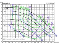
You should have received a performance curve specific to your pump when it was first shipped to you—whether it is a centrifugal or a positive displacement pump. The curve details a few things and, in the case of a centrifugal pump, should look like Figure 1. The pictured curve shows us:
- The differential head (pressure) that your pump should produce (y axis)
- Flow rates that correspond with the differential head (x axis)
- Efficiency of the pump (in green)
- Net Positive Suction Head required (NPSHr) (in purple)
- Impeller size (centrifugal pumps) (in black)
- Horsepower of your motor (in blue)
- RPMs of the motor (top right)
- Size of the pump casing—top left.
The first four bullet points are your four main pieces of information. You’ll want to watch these closely. The next two bullet points (impeller size and horsepower) are fixed, but changeable based on your needs. The final two are fixed.
Make sure you follow the curve that matches your impeller size. This will show you exactly where on the performance curve your pump is operating at any given time.
The relationship between differential head and flow is the most basic concept on the pump curve—more head equals less flow and vice versa. As head and flow vary, the pump’s performance will follow the curve relative to efficiency, suction head requirements, and the needed horsepower. Again, match your impeller size to the proper curve and you can track your pump performance.
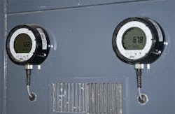
BEP is indicated where the curve intersects with the best possible efficiency on your graph. For most pumps, this is approximately 85 percent of maximum, or shut-off head. To keep your pump at or near BEP, the best thing you can do is train your pump operators to monitor the differential head. Set both high and low parameters of acceptable operation. The differential head is monitored using two pressure gauges—one on the suction nozzle and another on the discharge nozzle.
Both pressure gauges are necessary. The one at the suction nozzle is the more important of the two as it helps ensure that enough energy is coming into the pump. Too little suction pressure results in severe pump damage—ranging from broken seals and worn bearings to cavitation.
The gauge at the discharge nozzle is useless by itself. But when used together with the suction gauge it provides the differential head measurement and is useful for spotting downstream issues within the pump system.
Digital pressure gauges are highly recommended because they are much easier to read, much more reliable, will last much longer, and can send outputs to your control system. Adding a little automation will aid your pump operators in keeping your pumps near BEP. Those who use analog pressure gauges find they cannot leave them on the pump very long, as they quickly wear out resulting in an unmonitored pump. Installing a pair of digital pressure gauges on each pump, however, is the single best thing you could do for your pump operators and your maintenance budget.
What happens when my pump produces too little differential head?
There are really two scenarios here; either the suction or the discharge pressure is lacking. Your digital pressure gauges will tell you which is the case.
Starving your pump
If you don’t have enough pressure at the suction nozzle of your pump, the pump is starved. In other words, you don’t have enough energy coming into your pump. As you look at the differential head on your pump curve, you’ll notice it drags the performance to the right of BEP.
This will be indicated on both your suction and discharge gauges. If you have a flowmeter installed, you’ll also notice reduced flow.
When your pump is starved, there are a few bad things that happen. You’ll notice your pump vibrating loudly as vapor bubbles are formed inside your pump. These bubbles form and collapse as they travel from low to high-pressure zones inside the pump casing. This is called cavitation, and a starving pump is the most common cause.
The energy from the imploding bubbles is strong enough to create cavities on the surface of the impeller blades. The shock waves from the cavitation wreak havoc on your bearings and seals causing pre-mature failure.
This can happen if your operator is draining a tank and the level gets too low. It also happens naturally over time as build-up inside the suction pipes restricts flow to the pump, or suction-side filters gradually clog.
The only way to fix this is to increase the energy, or suction head, coming in to the pump. However, there are a number of ways to do so. Your operator can make sure that all the valves and suction pipe are completely open. He/she also needs to check all suction filters or strainer baskets to make sure they are clean. If there is no quick way to increase flow to the pump, you can refill the suction tank or use a variable frequency drive (VFD) to slow the speed of the pump.
You may need the engineer to install a booster pump between the suction tank and the pump. Your engineer can also have the suction side of the pump re-piped with oversize pipe and long radius elbows. Improper plumbing can reduce the suction head. For example, you should avoid filters on the suction side of a pump. Make sure you use shut-off valves and not control valves. Use 45 degree elbows instead of a 90 degree elbows.
Enough suction pressure, not enough discharge pressure
If you have enough energy coming into your pump, but your discharge pressure is inadequate, then the problem is completely different. Your differential pressure will also be inadequate, and drag your pump to the right on the performance curve.
In this case, there is too little downstream resistance and the pressure inside the pump casing (or volute) becomes imbalanced. This causes the entire shaft and impeller assembly to deflect to one side, resulting in rubbing and scraping where tolerances are very tight inside the pump. This is called shaft deflection. The impeller can scrape the pump casing, and the mechanical seal can rub against the inside of the seal chamber. This will cause the bearings to wear faster and unevenly.
This is the sort of damage that will put your pump in the maintenance shop rather quickly.
Notice that while this scenario looks similar on the performance curve to inadequate suction pressure, it is in fact totally different. Your pump operator must be able to interpret the pressure gauges effectively to determine what to do next.
The solution is simply to increase the downstream resistance. Your operator can restrict a discharge valve, increase the pressure in a downstream tank, or increase the elevation differential by filling a downstream tank.
Your discharge pressure will increase as you increase resistance downstream. This will pull your pump to the left on the performance curve—back to its BEP. As your pump comes back to BEP, the vibrations and cavitation will disappear and component failure will be avoided.
What happens when my pump produces too much differential head?
This means you have too much downstream resistance holding energy inside your pump. The excessive differential head drags your pump performance to the left of BEP.
In this scenario, your pump will over-heat and vibrate. This also causes shaft deflection, but due to an increase of pressure instead of a loss. The impeller and shaft assembly will deflect once again, but in the opposite direction, causing rubbing, wear, and premature failure.
Your pump will also start to cavitate as the temperature and pressure combine to create imploding vapor bubbles.
The best way to fix this is to look for the excessive downstream resistance. Perhaps you have a clogged filter, a closed valve, or build-up inside the pipes. If you’re filling a tank, perhaps the tank has become too full. Maybe the pressure is too high in a downstream tank or reactor vessel. Whatever the problem, your operator needs to either relieve the resistance, or shut off your pump.
With a little bit of the right training, a good pump operator can resolve these issues and extend the MTBF on your pumps. All you need to provide are two pressure gauges for each pump.
Take a deep breath
At the end of the day, pumps are fairly simple. But they must be operated properly—at or near BEP—in order to do the job right. You must think of pump control as more than just turning them on and off. Install digital pressure gauges on both the suction and discharge nozzles of your pumps. Keep enough energy coming into your pumps, and make sure the differential head is kept within the safe zone.
There is an answer to high maintenance pumps. Pull out your pump curves and use your pressure gauges to interpret them. Involve the maintenance techs, the instrumentation techs, the process engineer, the reliability engineer, and even the number crunchers in management. Working together as a team will make it a lot easier.
Once your pumps are humming happily along and your maintenance department has more free time and more money in the budget, you’ll be able to breathe easy. Your bearing and seal vendors may start to worry as you stop ordering so many parts. They’ll think you’re buying from somebody else. At the end of the day, you will find a big ROI as your pumps work without failure and your processes are uninterrupted.
Kelvin Findlay is an industry analyst and marketing manager at Automation Products Group Inc. He is deeply involved in APG’s pressure measurement product line for the Oil & Gas, Water & Wastewater, and Chemical industries. His passion for understanding how and why sensors are used in the field drives his research and APG’s product development. Mr. Findlay can be reached at [email protected] or 888 525-7300, ext. 1054.
